A
frame
for
four
servos
is
pro
-
vided
in
the
fuselage.
There
is
enough
mounting
space
for
two
elevator-,
a
rudder
and
a
tail
wheel
servo
in
standard size.
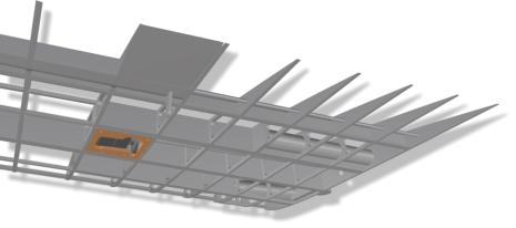
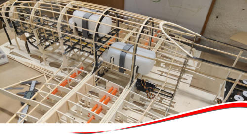
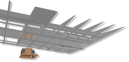
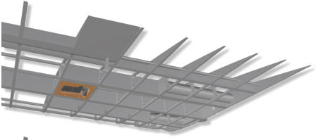
High-power LEDs (e.g. Seoul Emitter, 3.5 W) can be installed as position lighting in the wings and at the rear. Due to the
high core temperature, they must be applied to heat sinks using thermal adhesive. These are usually rodlike, made of
aluminum and have a diameter of 8 mm.
The
appropriate
mount
positions
have
already
been
structurally
prepared.
Control
via
constant
current
sources can be done by the
gearCONTROL.846
.
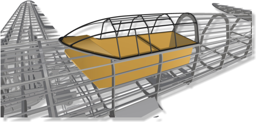
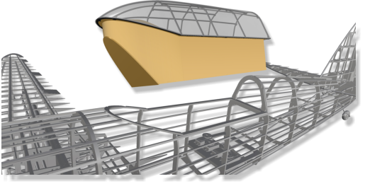
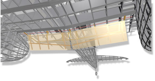
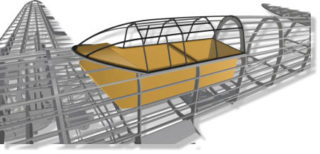
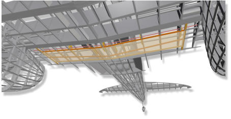
The
glare
shield,
an
area
for
the
instruments
panel
and
a
cockpit
tub
are
prepared
for
further
design
on
one´s
own.
Balsa
of
medium hardness is used here.
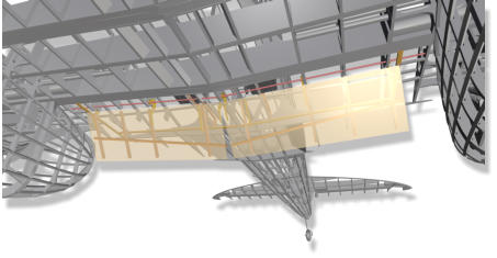
The
cockpit
unit
can
be
moved
out
in
one
piece.
To
lock,
pins
reach
into
the
fuselage
out
of
the
backside
of
the
unit.
The
unit
is
secured by a Bowden from the open nose.
In
order
to
model
the
cock
-
pit
canopy´s
typical
lattice
frame,
milled
fiber
glass
components
are
bonded
to
each
other.
This
results
in
a
stable
framework
to
be
glued
into the clear acrylic canopy.
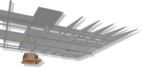
The
flaps
servos
can
either
be
inserted
and
screwed
from
below
through
the
flap
ope
-
nings
or
from
above
through
the
canopy
opening
into
two
vertical
servo
frames.
The
servo
arms
are
then
screwed
through
the
flap opening onto the servo drive.
The aileron servos sit in prepared frames that can be taken out of
the wing at any time, e.g. to replace a defective servo
drive.
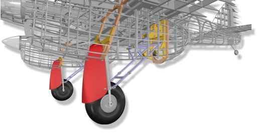
Seven
screws
keep
the
main
landing
gear
assembly
in
place.
It
can
be
mounted/dismounted
as
a
single
assembly
group
in
minutes.
The
brus
-
hless
outrunner
and
the
electronic
speed
c
o
n
t
r
o
l
l
e
r
(ESC)
are
quite
easily
accessible
through
the
landing gear opening either.
By
doing
without
a
removable
fiber
glass
cowling,
weight
could
be
saved.
The
wheels
have
a
diameter
of
125
mm.
The
wheel
pant
slides
a
bit
into
the
inte
-
rior of the nacelle with the gear being extended.


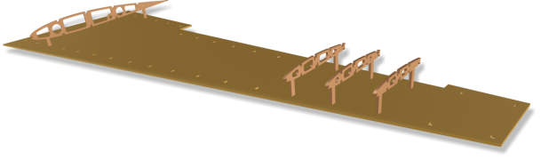
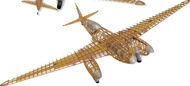
D.H. 88 Comet.


Technical Details.

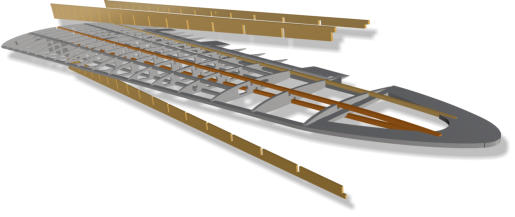
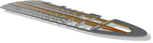
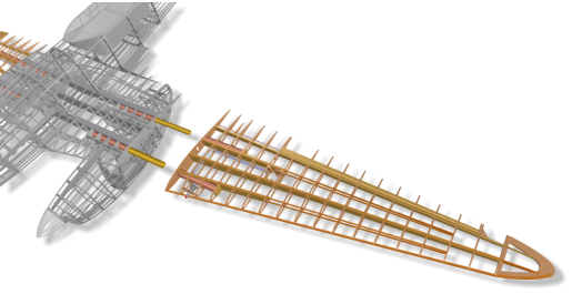
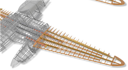
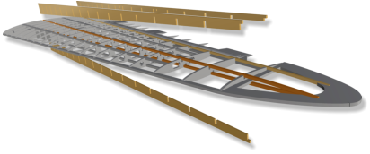
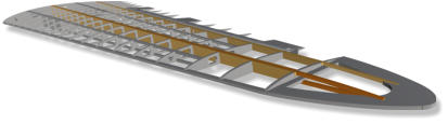
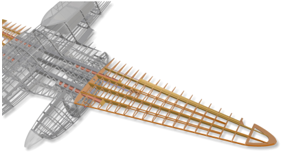
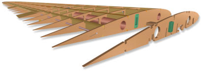
All
spars
arrangements
are
designed
as
„comb
boxes“.
That
is,
like
a
comb,
the
casing
elements
are
inserted
into
the
wing
along
the
spars
from
above
or
below.
This
leads
to
a
significant
reduction
in
construc
-
tion time.
6.
„Comb Boxes“
The places where the linkage cables are glued to the fuselage frames are already specified by design.
The
Bowden
tubes
thus
follow
a
perfect
curve
between
the
servo
and
the
rudder
horn,
which
has
the
largest
possible
radii.
This minimizes the friction of the cores and the rudder lash.
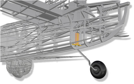
Unlike
the
original
Comet
,
which
has
a
tail
skid,
the
glattCAD
model
has
been
given
a
relatively
simple
tail
wheel
for
better
practicality.
Its
rede
-
sign
should
therefore
be
reserved
for
the
(scale)
modeller,
if
desired.
The
steering
is
carried
out
via
two
steel
braids.
Fiber
glass
rudder
horn,
spring
steel,
wheel,
adjusting
rings
and
steel
braid
are
included in the kit.
5.
Tail Wheel
9.
Cockpit Unit
Rudder,
elevator
and
ailerons
move
in
fillets.
The
axles
consist
of
core
and
0.8
mm
spring
steel
of
standard
Bowden
cables,
which
are
normally
used
for
controlling
rudders
of
all
types.
They
are
pulled
out
of
the
tubules
at
the
side
or
top,
so
that
the
rudder
blades
can
be
easily
removed
at
any
time.
All
rudder
horns
are
included
in
the
kit
as
milled
fiber
glass
parts.
They
are
bonded
in
the
front
balsa
elements
of
the
rudders.
This
results
in
reliable
and
practical controls.
The
vertical
and
horizontal
tail
fins
are
built
without
the
help
of
special
jigs.
Instead
locating
ele
-
ments
in
the
regarding
fuselage´s
area
guarantee
right-angle
and
rail-guided
bonding.
Rudder
and
elevators
are
placed
on
jigs
and
still
covered
there
with
balsa
on
the
upper
side.
As
already
mentioned
above,
all
jigs
can
be
(quickly)
remo
-
ved
from
the
assembly
table
at
any build stage and be located elsewhere without
risking warpage!
10.
Rudder
12.
Servo Frames
Further
back
in
the
battery
duct,
the
bat
-
tery
carrier
abutment
can
be
seen.
A
removable
aluminium
pin
in
the
middle
allows
the
abutment
to
be
relocated.
The
5.5mm
„gold
contacts“
glued
into
it
auto
-
matically
provide
the
electrical
connection
when
pushing
the
carrier
backwards.
They
also
contribute
to
secure
keep
the
battery
in
position.
In
addition
it
is
secured
from
the front.
An
unintentional
twisting
of
the
abutment
is
constructively
prevented
by
means
of
a
pine rod directing backwards. It can be reached through the canopy opening.
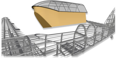
The
fuselage
nose
is
removable.
It
is
secured
by
four
strong,
guided
pin
magnets,
which
adhere
to
four
flat
magnets
on
the
fuse
side.
These
will
be
glued
to
the
back
of
the
four
balsa
blocks
visible
in
the
picture
above.
The
linear
guide,
com
-
bined
with
the
rare
earth
magnets,
reliably
ensure
that
the
nose
cannot bid goodbye in flight.
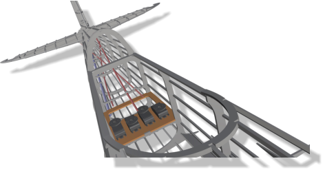
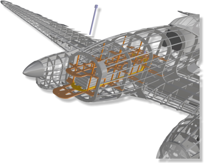
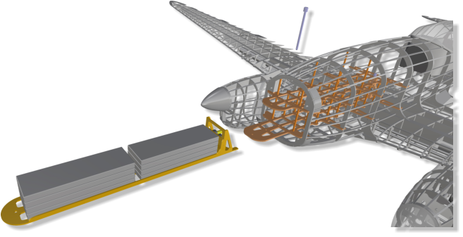
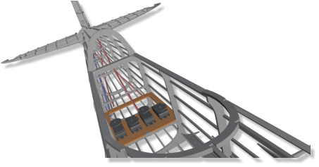
The
battery
pack
fixed
on
a
fiber
glass
carrier
is
inserted
from
the
front
into
the
appropriate
duct.
The
series
of
pictures
on
the
right
shows,
from top to bottom, how to take the battery pack out.
The
battery
duct
is
filigree
and
robust
at
the
same
time.
It
allows
the
fiber
glass
battery
carrier
to
be
locked
in
various
defined
positions.
Small,
milled,
circular
holes
in
the
duct´s
two
protruding tongues serve this purpose.
This
concept
offers
the
advantage
to
precisely
adjust
the
center
of
gravity
at
any
time
and
without
any
structural
change.
In
the
front
area,
under
the
duct,
a
receiver
battery
and
a
battery
to
power
the retractable landing gear can be stowed away.
7.
Battery Pack
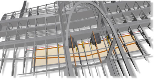
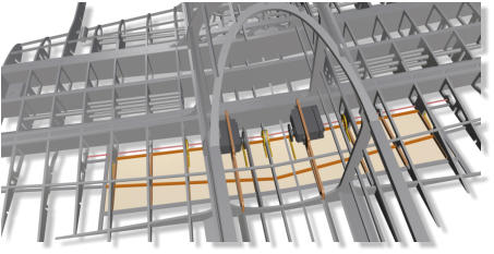
Each
core
or
cable
that
is
to
be
run
over
a
longer
distance
in
the
model
lies
in
a
thin-
walled
tube.
Long
party
straws
are
used
for
this
purpose.
The
corresponding
circu
-
lar
holes
were
specially
designed
in
the
related
components.
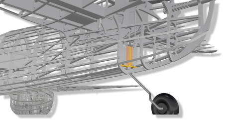
The
wire
ducts
(orange)
of
the
central
electrical
connec
-
tion
between
the
fuselage
and
the
wing
is
shown.
8.
Wire Ducts
It
is
suffi
-
cient
to
secure
the
jig
with
a
few
weights
or
needles
on
the
construc
-
tion
table
against
slipping.
As
soon
as
a
few
more
components
have
been
instal
-
led,
a
fuselage
or
a
wing
half
can
be
easily
transported
to
another
work
station
together
with
the
jig.
Any
table
or
a
door
from
the
hardware
store
with
the
dimensi
-
ons
165
cm
x
78
cm
is
perfect
as
a
building
board for the assembly.
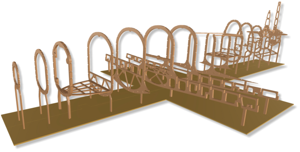
Formers,
wings-
and
empen
-
nage
ribs
are
equipped
with
small
„legs“.
They
are
put
into
the
corresponding
slot
of
the
poplar
plywood
„jig“.
A
war
-
page
in
assembly
is
practically
impossible,
provided
that
a
straight
construction
table
is used as a base.
1.
Jigs
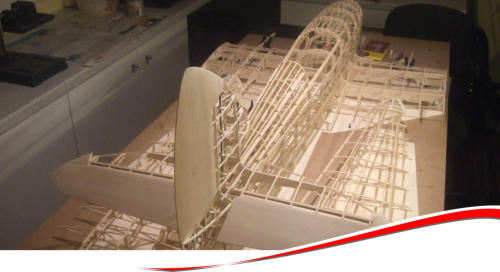
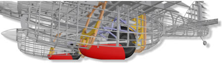
2.
Main Frames
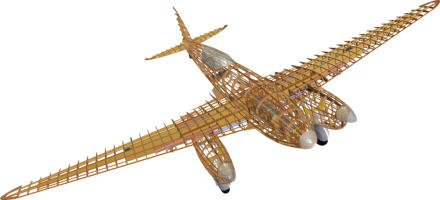
With
the
full-length
double
spar
pairs
made
of
pine
wood
and
the
balsa
on
the
front
and
back,
the
two
main
frame
boxes
are
very
sturdy
while
being lightweight.
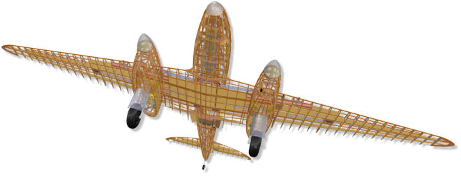
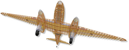
The
central
piece
of
the
Comet
includes
the
two
engine
nacelles
with
the
undercarriages
mounted
in
them.
The
width
is
78.5
cm
and
can
be
easily
put
in
a
car
with
folded
rear
seats
for
transport.

Accessories Recommendation.
• 2 brushless outrunners e. g.: 400 .. 450 gr, Ø 50 mm, length 60..65 mm, KV = 250 .. 300 U/min/V • 2 HV electronic speed controllers 50 .. 80 A • Lipo 8s, 5000 .. 5800 mAh • 2 two-blade propellers ca. 15" x 12", best: left- and right-turning • 2 spinners Ø 76 mm • LED-lighting (according to your own idea; see also manual for gearCONTROL.846) • Wheels Ø 125 mm, width 45 mm
An
electrical
connector
system
is
required
to
control
the
servo
and
the
LED
position
light
installed
in
the
outer
wing.
The
corresponding
slots
for
installing
“multiplex”
connectors
are
already milled into the root ribs.
A
high-quality
STRONGAL®
fuselage-surface
connection
from
Petrausch
Modellbau
with
16mm
pipe
thickness
ensures
safety.
Due
to
the
jig
system
explained
above,
an
absolutely
par
-
allel duct of the two tubes in the fuselage central piece and outer wings is guaranteed.
3.
Wing Connectors
Flight Properties.
For the development of the glattCAD D.H 88 Comet , a number of important parameters were analyzed and determined by software. They were incorpo - rated in the construction. The Reynolds effect was counteracted with the implementation of a moderate twist from the root ribs towards the tips at the expense of aerobatic capability. Fow slow loops, this causes the glattCAD Comet to fall out of the figure at the apex. This can also happen during inverted flight. That these maneu - vers do not really want to succeed is the price paid for more aileron effectiveness and safety. You can live with that, because the original Comet was not intended for such maneuvers either. In order to improve the dynamic stability around the z- axis, the tail surfaces have been slightly enlarged to improve the chance to react on an engine failure (combustion engine). The theory´s correctness has been confirmed in practice with excellent results! However certain peculiarities shall also not be concealed which could only be countered by design features to a limited extent. It takes a bit getting used to the Comet´s take-off behaviour, since it shows the ususal breakout attempts typical of a twin-engined plane. But experience proved that this bad habit can be eliminated with the installation of a modern electronic gyroscope. Counter-rotating propellers are also recommended. When landing, the gyro has another useful task: As a model with a conventional (taildrag - ger) undercarriage, the glattCAD Comet also tends to jump if the landing is not optimal. As soon as the tailplane bobs downwards at touch-down, the large underside area of the fuselage together with the wings´typical, rear - ward-pulled trailing edges at the root ribs support the tendency to bounce. A gyro per - fectly eliminates this rotation about lateral axis. The glattCAD Comet is designed to be driven by two brushless outrunners, but she can also be equipped with combustion engines. On request, suitable firewalls for the rear wall mounting are supplied for the chosen combustion motors.

A Comet as an RC model?
Sometimes the Comet is said to be „difficult to fly“, because of her incompa - rably elegant wing outline. It is said that she tends to sudden stalls and is not easy to pilot basically. Some constructive weaknesses are inevitably „impor - ted“ from the original aircraft. The strikingly tapered wing tips of the original aerodynamically may not be an issue for the full-scale Comet . In a quarter scale model, however, the running length of the air flow in the area of the outer wings is worryingly short. Moreover the flight speed is correspondingly lower. In the tip area of the wing, where small and larger flow detachments actually have to be parried with the ailerons, these are no longer fully effec - tive as a result of the physically unavoidable Reynolds effect - also known as the „scale effect“. The flight characteristics of a model aircraft depends on the design of its wings to a large extent. The „scale effect“ would best be faced by defusing the taper (apart from increasing the flight speed), because this would incre - ase the running length of the airflow. However, this is forbidden if you do not want to change the outline (top view) of the model. It is better to smartly select the wing airfoils and their distribution over the span. Naturally, Mr. Reynolds does not strike so hard, when the angle of attack of a cambered airfoil will be reduced to the outside. This measure is acceptable in terms of keeping to the outlines of the original aircraft, because it is prac - tically invisible. The RC model´s static and dynamic intrinsic stability via its three axes must be „preset“ constructively. In this regard, too, interventions in the outline of the model are largely forbidden. Again other variables depend on the stabi - lity, for example the landing speed, which is partly determined by the effectiveness of the flaps.
The
undercarriage
kit
is
available
in
the
shop,
except
the
wheels.
It
includes
a
grinding
aid
of
milled
MDF
for
preparing
the
steel
tubes.
The
grinding
aid
has
some
grooves
and
holes,
so
that
the
tubes
can
be
prepared
for
hard-
soldering.
Similarly,
a
jig
made
of
milled
ver
-
miculite
helps
to
align
the
prepared
tubes
perfectly
to
each
other
for
the
welding process and to fix them on the fireproof material.
4.
Main Landing Gear
The
landing
gear
is
retracted
and
extended
by
a
small
geared
12V
DC
motor
that
drives
a
spindle
on
which
the
drive
nut
slides.
Waterproof
micro
switches
can
be
used
to
detect
the
end
position
and
switch
off
the
geared
motor.
The
switching
states
can
be
read
and
processed
by
the
glattCAD
gearCONTROL.846
.
In
addition,
this
small
controller
can
also
switch
the
landing headlight, and the rear and wing position lightings.

11.
Flaps
The flaps are two-piece, as with the
great original Comet.
13.
Position Lights
The
wire
pairs
can
be
sto
-
red
cleanly
in
plastic
tubes
through
the
wing
ribs,
respectively
fuselage
for
-
mers.


Build Manual.
D.H. 88 Comet


Build Manual.
D.H. 88 Comet


Build Manual.
D.H. 88 Comet


Build: Ludwig Retzbach
Erbauer: Ludwig Retzbach
Technical Data.
Scale: 20% Wingspan: 268 cm Length: 177 cm Take-off weight: 7 .. 11 kgTechnical Data.
Scale: 20% Wingspan: 268 cm Length: 177 cm Take-off weight: 7 .. 11 kgTechnical Data.
Scale: 20% Wingspan: 268 cm Length: 177 cm Take-off weight: 7 .. 11 kgTechnical Data.
Scale: 20% Wingspan: 268 cm Length: 177 cm Take-off weight: 7 .. 11 kg


© 2020-06 glattCAD Flugmodelle Christoph Glatt Bauernstr. 77 86462 Langweid am Lech
Info@glattCAD.de


D.H. 88 Comet.


All
spars
arran
-
gements
are
designed
as
„comb
boxes“.
That
is,
like
a
comb,
the
casing
elements
are
inserted
into
the
wing
along
the
spars
from
above
or
below.
This
leads
to
a
signifi
-
cant reduction in construction time.
A
frame
for
four
servos
is
provided
in
the
fuselage.
There
is
enough
mounting
s
p
a
c
e
for
two
elevator-,
a
rudder
and
a
tail
wheel
servo
in
stan
-
dard size.
Rudder,
elevator
and
ailerons
move
in
fillets.
The
axles
consist
of
core
and
0.8
mm
spring
steel
of
standard
Bowden
cables,
which
are
normally
used
for
controlling
rudders
of
all
types.
They
are
pulled
out
of
the
tubules
at
the
side
or
top,
so
that
the
rud
-
der
blades
can
be
easily
removed
at
any
time.
All
rudder
horns
are
included
in
the
kit
as
milled
fiber
glass
parts.
They
are
bonded
in
the
front
balsa
ele
-
ments
of
the
rudders.
This
results
in
reliable
and
practical controls.
The
vertical
and
horizontal
tail
fins
are
built
without
the
help
of
spe
-
cial
jigs.
I
n
s
t
e
a
d
locating
elements
in
the
regarding
fuselage´s
area
guarantee
right-angle
and
rail-guided
bonding.
Rud
-
der
and
elevators
are
placed
on
jigs
and
still
covered
there
with
balsa
on
the
upper
side.
As
already
mentioned
above,
all
jigs
can
be
(quickly)
removed
from
the
a
s
s
e
m
b
l
y
table
at
any
build
stage
and
b
e
located elsewhere without risking warpage!

Further
back
in
the
battery
duct,
the
battery
carrier
abutment
can
be
seen.
A
removable
aluminium
pin
in
the
middle
allows
the
abutment
to
be
relocated.
The
5.5mm
„gold
contacts“
glued
into
it
automati
-
cally
provide
the
electrical
connection
when
pushing
the
carrier
backwards.
They
also
contribute
to
secure
keep
the
battery
in
position.
In
addition
it
is
secured from the front.
An
unintentional
twisting
of
the
abutment
is
con
-
structively
prevented
by
means
of
a
pine
rod
direc
-
ting
backwards.
It
can
be
reached
through
the
canopy opening.
T
h
e
f
u
s
e
l
a
g
e
nose
is
remova
-
ble.
It
is
secured
by
four
strong,
guided
pin
magnets,
which
adhere
to
four
flat
magnets
on
the
fuse
side.
These
will
be
glued
to
the
back
of
the
four
balsa
blocks
visible
in
the
picture
above.
The
linear
guide,
combined
with
the
rare
earth
magnets,
reliably
ensure that the nose cannot bid goodbye in flight.
The
battery
pack
fixed
on
a
fiber
glass
carrier
is
inserted
from
the
front
into
the
appropriate
duct.
The
series
of
pictures
on
the
right
shows,
from
top
to
bottom,
how
to
take
the
battery
pack out.
The
battery
duct
is
fili
-
gree
and
robust
at
the
same
time.
It
allows
the
fiber
glass
battery
carrier
to
be
l
o
c
k
e
d
in
various
defined
positions.
Small,
milled,
circular
holes
in
the
duct´s
two
protruding
tongues serve this purpose.
This
concept
o
f
f
e
r
s
the
advantage
to
precisely
adjust
the
center
of
gravity
at
any
time
and
without
any
structural
change.
In
the
front
area,
under
the
duct,
a
receiver
bat
-
tery
and
a
battery
to
power
the
retractable
landing gear can be stowed away.


F
o
r
-
mers,
wings-
and
empennage
ribs
are
equipped
with
small
„legs“.
They
are
put
into
the
corresponding
slot
of
the
poplar
plywood
„jig“.
A
warpage
in
assembly
is
practically
impossible,
provided
that
a
straight
con
-
struction table is used as a base.

A
high-quality
STRONGAL®
f
u
s
e
l
a
g
e
-
s
u
r
f
a
c
e
c
o
n
n
e
c
t
i
o
n
f
r
o
m
Petrausch
Modellbau
with
16mm
pipe
thickness
ensures
safety.
Due
to
the
jig
system
explained
above,
an
absolu
-
tely
parallel
duct
of
the
two
tubes
in
the
fuselage
central
piece
and
outer
wings
is
guaran
-
teed.
Seven
screws
k
e
e
p
the
main
landing
gear
a
s
s
e
m
b
l
y
in
place.
It
can
be
mounted/dismounted
as
a
single
assembly
group
in
minutes.
The
brushless
outrunner
and
the
electronic
speed
controller
(ESC)
are
quite
easily
accessible
through
the
landing
gear
opening either.
By
doing
without
a
removable
fiber
glass
cowling,
weight
could
be
saved.
The
wheels
have
a
diameter
of
125
mm.
The
wheel
pant
slides
a
bit
into
the
inte
-
rior of the nacelle with the gear being extended.
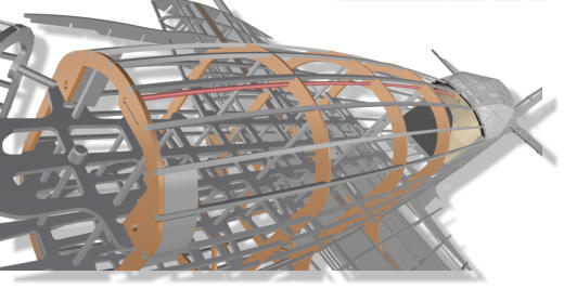
High-power LEDs (e.g. Seoul Emitter, 3.5 W) can be
installed as position lighting in the wings and at the
rear. Due to the high core temperature, they must
be applied to heat sinks using thermal adhesive.
These are usually rodlike, made of aluminum and
have a diameter of 8 mm.
The
appro
-
priate
mount
p
o
s
i
t
i
o
n
s
have
already
been
structurally
prepared.
Control
via
constant
current
sources
can
be
done
by
the
gear
-
CONTROL.846
.


Technical Data
Scale: 20% (1:5) Wingspan: 268 cm Length: 177 cm Take-off Weight: 7 .. 11 kgBuild Manual
D.H. 88 Comet

A Comet as an RC model?
Sometimes the Comet is said to be „difficult to fly“, because of her incomparably elegant wing outline. It is said that she tends to sudden stalls and is not easy to pilot basically. Some constructive weaknes - ses are inevitably „imported“ from the original aircraft. The strikingly tapered wing tips of the origi - nal aerodynamically may not be an issue for the full-scale Comet . In a quarter scale model, however, the running length of the air flow in the area of the outer wings is worryingly short. Moreover the flight speed is correspon - dingly lower. In the tip area of the wing, where small and lar - ger flow detachments actually have to be parried with the aile - rons, these are no longer fully effective as a result of the physically unavoida - ble Reynolds effect - also known as the „scale effect“. The flight characteri - stics of a model air - craft depends on the design of its wings to a large extent. The „scale effect“ would best be faced by defusing the taper (apart from increa - sing the flight speed), because this would increase the running length of the airflow. However, this is for - bidden if you do not want to change the outline (top view) of the model. It is better to smartly select the wing airfoils and their distribution over the span. Naturally, Mr. Reynolds does not strike so hard, when the angle of attack of a cambered airfoil will be reduced to the outside. This measure is acceptable in terms of keeping to the out - lines of the original aircraft, because it is practically invisible. The RC model´s static and dynamic intrinsic stability via its three axes must be „preset“ constructively. In this regard, too, interventions in the outline of the model are largely forbidden. Again other variables depend on the stability, for example the landing speed, which is partly determi - ned by the effectiveness of the flaps.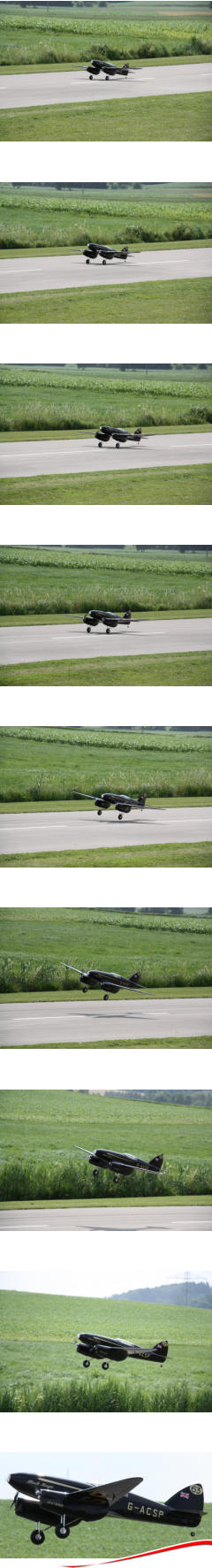

Flight Properties.
For the development of the glattCAD D.H 88 Comet , a number of important parameters were analyzed and determined by software. They were incorpora - ted in the construction. The Reynolds effect was counteracted with the implementation of a mode - rate twist from the root ribs towards the tips at the expense of aerobatic capability. Fow slow loops, this causes the glattCAD Comet to fall out of the figure at the apex. This can also happen during inverted flight. That these maneu - vers do not really want to succeed is the price paid for more aileron effectiveness and safety. You can live with that, because the original Comet was not intended for such maneuvers either. In order to improve the dynamic stability around the z- axis, the tail surfaces have been slightly enlarged to improve the chance to react on an engine failure (combustion engine). The theory´s correctness has been confirmed in practice with excellent results! However certain peculiarities shall also not be con - cealed which could only be countered by design features to a limited extent. It takes a bit getting used to the Comet´s take-off behaviour, since it shows the ususal breakout att - empts typical of a twin-engined plane. But experi - ence proved that this bad habit can be eliminated with the installation of a modern electronic gyros - cope. Counter-rotating propellers are also recom - mended. When landing, the gyro has another useful task: As a model with a conventional (taildragger) undercar - riage, the glattCAD Comet also tends to jump if the landing is not optimal. As soon as the tailplane bobs downwards at touch-down, the large underside area of the fuselage together with the wings´typical, rearward- pulled trailing edges at the root ribs support the ten - dency to bounce. A gyro per - fectly eliminates this rotation about lateral axis. The glattCAD Comet is desi - gned to be driven by two brushless outrunners, but she can also be equipped with combustion engines. On request, suitable fire - walls for the rear wall mounting are supplied for the chosen combustion motors.


Accessories Recommenda-
tion.
• 2 brushless outrunners e. g.: 400 .. 450 gr, Ø 50 mm, length 60..65 mm, KV = 250 .. 300 U/min/V • 2 HV electronic speed controllers 50 .. 80 A • Lipo 8s, 5000 .. 5800 mAh • 2 two-blade propellers ca. 15" x 12", best: left- and right-turning • 2 spinners Ø 76 mm • LED-lighting (according to your own idea; see also manual for gearCONTROL.846) • Wheels Ø 125 mm, width 45 mm
It
is
sufficient
to
secure
the
jig
with
a
few
weights
or
needles
on
the
construction
table
against
slipping.
As
soon
as
a
few
more
components
have
been
installed,
a
fuselage
or
a
wing
half
can
be
easily
transported
to
another
work
station
together
with
the
jig.
Any
table
or
a
door
from
the
hardware
store
with
the
dimensions
165
cm
x
78
cm
is
perfect
as
a
building board for the assembly.
With
the
full-length
double
spar
pairs
made
of
pine
wood
and
the
balsa
on
the
front
and
back,
the
two
main
frame
boxes
are
very
sturdy
while
being
light
-
weight.
The
central
piece
of
the
Comet
includes
the
two
engine
nacelles
with
the
undercarriages
mounted
in
them.
The
width
is
78.5
cm
and
can
be
easily
put
in
a car with folded rear seats for transport.
An
electrical
connector
system
is
required
to
control
the
servo
and
the
LED
position
light
installed
in
the
outer
wing.
The
corresponding
slots
for
instal
-
ling
“multiplex”
connectors
are
already
milled
into
the root ribs.


The
undercarriage
kit
is
available
in
the
shop,
except
the
wheels.
It
includes
a
grinding
aid
of
milled
MDF
for
preparing
the
steel
tubes.
The
grinding
aid
has
some
grooves
and
holes,
so
that
the
tubes
can
be
prepared
for
hard-soldering.
Similarly,
a
jig
made
of
milled
vermiculite
helps
to
align
the
prepared
tubes
perfectly
to
each
other
for
the
welding
process
and
to fix them on the fireproof material.
The
landing
gear
is
retracted
and
extended
by
a
small
geared
12V
DC
motor
that
drives
a
spindle
on
which
the
drive
nut
slides.
Waterproof
micro
swit
-
ches
can
be
used
to
detect
the
end
position
and
switch
off
the
geared
motor.
The
switching
states
can
be
read
and
processed
by
the
glattCAD
gear
-
CONTROL.846
.
In
addition,
this
small
controller
can
also
switch
the
landing
headlight,
and
the
rear
and
wing position lightings.
Build Manual
D.H. 88 Comet
Unlike
the
original
Comet
,
which
has
a
tail
skid,
the
glattCAD
model
has
been
given
a
relatively
simple
tail
wheel
for
better
practicality.
Its
redesign
should
therefore
be
reserved
for
the
(scale)
modeller,
if
desired.
The
steering
is
carried
out
via
two
steel
braids.
Fiber
glass
rudder
horn,
spring
steel,
wheel,
adjusting
rings
and
steel
braid
are
included
in
the
kit.


Build Manual
D.H. 88 Comet


Build Manual
D.H. 88 Comet
Each
core
or
cable
that
is
to
be
run
over
a
longer
distance
in
the
model
lies
in
a
thin-walled
tube.
Long
party
straws
are
used
for
this
purpose.
The
corresponding
circular
holes
were
specially
desi
-
gned
in
the
related
components.
The
wire
ducts
(orange)
of
the
central
electrical
connection
bet
-
ween the fuselage and the wing is shown.
The
glare
shield,
an
area
for
the
instruments
panel
and
a
cockpit
tub
are
prepared
for
further
design
on
one´s own. Balsa of medium hardness is used here.
The
cockpit
unit
can
be
moved
out
in
one
piece.
To
lock,
pins
reach
into
the
fuselage
out
of
the
backside
of
the
unit.
The
unit
is
secured
by
a
Bowden
from
the open nose.
In
order
to
model
the
cockpit
canopy´s
typical
lat
-
tice
frame,
milled
fiber
glass
components
are
bonded
to
each
other.
This
results
in
a
stable
frame
-
work to be glued into the clear acrylic canopy.
The
flaps
servos
can
either
be
inserted
and
screwed
from
below
through
the
flap
openings
or
from
above
through
the
canopy
opening
into
two
vertical
servo
frames.
The
servo
arms
are
then
screwed
through the flap opening onto the servo drive.
The flaps are two-piece, as with the great original
Comet.
The aileron servos sit in prepared frames that can
be taken out of the wing at any time, e.g. to replace
a defective servo drive.
The
places
where
the
linkage
cables
are
glued
to
the
fuselage frames are already specified by design.
The
Bowden
tubes
thus
follow
a
perfect
curve
bet
-
ween
the
servo
and
the
rudder
horn,
which
has
the
largest
possible
radii.
This
minimizes
the
friction
of
the cores and the rudder lash.
The
wire
pairs
can
be
stored
cleanly
in
plastic
tubes
through the wing ribs, respectively fuselage formers.
Builder: Ludwig Retzbach
Builder: Ludwig Retzbach
© 2020-06 glattCAD Flugmodelle Info@glattCAD.de
Christoph Glatt Bauernstr. 77 86462 Langweid am Lech